Formula Student: FSUK 2016

The Southampton University Formula Student Team has worked all year to produce Stag 3, its 2016 Formula Student contender. With the lightest, fastest, and most advanced vehicle that the team has produced to date, we went into the summer with high hopes of a good finish at the events.

The Silverstone event was our best ever finish in the UK, and then strong performance in the dynamic events in the Czech Republic led to a 14th place finish in a European event. Things did not go entirely smoothly along the way, but overall the results are just reward for the efforts of the team in 2016, and provide a very strong starting point for the 2017 car.

This article covers the manufacturing and logistics that have gone in to getting the car ready for two events, and some of the work behind the scenes which is already going on to prepare the team for the 2017 racing season.

Stag 3
Stag 3 at FSUK

The Build-Up

Manufacturing of the car started early in the year with the chassis, and continued in earnest at Easter with a big push on suspension, aerodynamics, and drivetrain components. The process was more carefully scheduled and controlled this year, learning from the mistakes of the previous year.

A list was kept of all of the components which needed to be manufactured, along with the processes required. This optimised our use of resources, so that as soon as a tool or machine became available it could be used.

We have a significant restriction in our build because we are only permitted to use power tools inside the university workshops, which are open 8-4:30 five days a week. This time forces us to be careful about planning machining operations and preparing materials and templates so that we can jump on and get the job done as soon as quickly as possible.

The build was paused during our exam period in May, and resumed at the start of June. A number of issues were found with the car when we came back after exams – fresh eyes and a break are always recommended because it is very easy to get tunnel vision on certain issues. We had a lot of work to do before the launch of the car at the University’s design show in the middle of June.

Due to conflicts with the university’s Eco-Marathon team, a number of parts which had been outsourced to the EDMC were over a month behind schedule arriving. Let that be another lesson – avoid scheduling conflicts and communicate with people who are sharing the same resources. It emerged that in order to present the car in a ‘mechanically complete’ form, we would have to improvise some uprights. The geometry of the uprights is such that this is not an easy task.

In the space of around three hours, MDF uprights were designed, laser-cut, glued together, and assembled to the car. We had no idea whether they would hold the weight of the car, but 6mm MDF seemed to be pretty strong.

Stag 3 at launch.
Stag 3 after launch. The wooden uprights and cling film tyres are clearly visible.

The car was painted in the evening and then assembled, from the chassis outwards, overnight. This was the first time that the suspension had been bolted to the car in full, and it was testament to the massive improvements in manufacturing processes that it slotted into place first time. The car was packed up and taken to the design show in the morning, and covered in a delightfully coloured tarpaulin ready for launch.

The Launch

The car was launched at the opening to the university design show, which is a major attraction to business, industry, and academia. The opportunity to present the car to a distinguished crowd opens the team up for praise and criticism in equal measure – plenty of photo opportunities and people keen to get a look, but also lots of questioning from those keen to challenge some of our design decisions. This makes for good practice for the design presentation itself.

Stag 3 with SUFST
The team presenting Stag 3 at the University Design Show

As the first year that we have had wings on the car, there was plenty of interest in the aerodynamic features of the car, along with several comments about the carbon suspension and the cling film wrapped around the tyres to protect the rubber. Nobody mentioned the wooden uprights…

The launch event was very successful overall, beating previous years where we have struggled to get a complete car out on show. The interest in the car was very encouraging, and the work done to get the car mechanically ready well in advance of the race season proved to be very beneficial.

FSUK

Over the next few weeks, several more long shifts were pulled to get the powertrain and electronics ready for competition. The final few outsourced components trickled in and were assembled onto the car; the MDF uprights were replaced with their aluminium alternatives and the spare set of wishbone inserts arrived ready for manufacture of backup suspension.

The last remaining part to come back was the throttle body – a fairly critical part of the whole intake system. While waiting for the new intake system, we tested the car with our intake from 2015. The 2015 intake didn’t meet 2016 regulations, so could only be used for our testing and would have to be swapped out before the event. The testing was very successful – the car was quick, seemed to be reliable, and didn’t exhibit any major mechanical flaws after the shakedown.

Testing continued for a few days to stress the components repeatedly – brake tests and acceleration runs were practiced to put the suspension and powertrain systems at full load. Both responded fairly well, so we took the car to Silverstone with high hopes of a good result.

Stag 3 with R J Mitchell
Stag 3 parked outside the R J Mitchell wind tunnel at Southampton University

The intake was finally finished on the Thursday of the event, so it was driven up separately and assembled on to the car at Silverstone. In the process of changing the intake, however, we discovered a number of metal components in the sump – never a good sign. It emerged that these were parts of the oil pump, which had failed at some point during testing.

We acquired a new oil pump from our spare engine (in Southampton) and fitted it on Friday, eventually getting through technical scrutineering late that afternoon. We moved on to the noise and brake test on Saturday, but had trouble getting the engine started. We continued to tweak the engine mapping, to try and get the engine to start, but it was never running for more than a couple of seconds at a time… and even then, it needed the throttle fully open to idle.

Despite spending all of Saturday and most of Sunday trying to get the engine running, it still wouldn’t cough in to life so we couldn’t pass the noise test. After getting the car back to Southampton, it emerged that the oil pump failure had caused the piston rings to melt, essentially writing off the engine. It was difficult to tell whether this failure had occurred in testing or at the event, but nonetheless it was clear that we were going to need the spare engine for our next event.

Although we didn’t pass scrutineering, the event was positive for a number of reasons. Firstly, we achieved our highest ever points total and highest ever finishing position at FSUK, courtesy of excellent scores in the design and business presentations. The team is getting quite accomplished at the static events. Secondly, one of our team members, Alvaro Sanchez Vela, was selected for the ‘Most Valuable Team Member’ award. It was absolutely deserved as his dedication to the team this year has been second-to-none.

FSUK was won in the end by Rennteam Stuttgart – a historic win for a combustion car in the era of electrical dominance. This followed the disqualification of a number of top electric teams for a variety of infringements, including aerodynamic exclusion zones (Delft) and exceeding power limits (Zurich). The lesson taken from the event is that speed is one thing, but that taking care to meet the regulations and design within the limits of the rules is part of the challenge. The Deflt team walked out of the awards ceremony as a protest against their disqualification, attracting much disdain from the remaining teams. The spirit of the competition is just as important as ever.

FS Czech

After Silverstone, the team returned to Southampton to prepare for the event at Autodrom Most, in the Czech Republic. In addition to changing the engine and properly fitting and testing the as-yet untested intake system, more dynamic testing was done. This revealed some weaknesses in the lower wishbones – they were clashing with the tyres due to rear toe compliance, leading to the press-fit bearings coming out of the inserts.

Repairs were made to the wishbones using the spare inserts, and the toe compliance was given a temporary fix. After a little more testing, the car was ready to travel to the event. Transport was courtesy of one of the university’s UAV support vans. This was offered free for the whole week of the event, giving us a base which was the envy of the paddock.

Building on our results from Silverstone, and with two weeks of testing offering much better reliability, we started all of the dynamic events. A 14th place finish was just reward for the team’s efforts this year. Unfortunately, a brake issue meant that we couldn’t finish the endurance, and we could have finished even higher up the field.

The wet conditions on Friday gave us an opportunity to test the car in more slippery conditions. Our drivers gave the crowd plenty to cheer about, with a number of pirouettes keeping the observers entertained. We also set some very competitive times, proving that all of the work done this year to improve the vehicle performance has paid off, and we have a very fast baseline to work from for 2017.

Autodrom Most
Wet conditions at Most gave us an opportunity to test the car in low-grip conditions.

2016 Handover

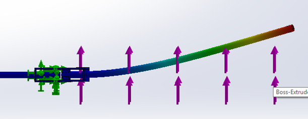
In the lead-up to the events, a huge handover process took place between the current committee and the next committee. The incoming team were elected around May, and since then I have worked on a handover document which explains the processes used to design and build the suspension system. It also covers a lot of the problems that have occurred in 2016, and offers suggestions to improve this for 2017.Suspension Handover Cover Page

Also included are walkthroughs of all of the tools and software we have used this year. Any scripts and code which has been written was documented and included, so that there is a reference for any future group leaders to refer to if they need to use the software or experience problems with it there is a guide which will allow them to fix it.

Recommendations are made within the document, and suggestions of areas to focus on for improvement are listed. However, there is a limit to the amount that can be transferred. Specific areas to change, blueprints and brand new designs, and direct instructions for the 2017 season are avoided. This both encourages the new group leaders to take ownership of their own design, and forces the information to be relevant for any year in the future of the team.

Suspension Handover Word Count
No such thing as ‘too much information’…

The document stretched to well over 50 pages, and was handed over with all of the documentation, software, and CAD files we have developed this year. The hope is that the new group leaders will be able to use this information as a starting point, and then take on their own ideas to develop and produce new concepts.

I would recommend writing something like this to every group and team leader in the Formula Student world. Knowledge transfer between years is vital to the success of the team over multiple years. Writing things down also reinforces the knowledge that has been acquired during the year; similarly, documenting code and cataloguing content produced during the year encourages it to be written well and produced carefully in the first place.

The handover process also included a number of meetings to pass information through face-to-face, and this form of knowledge transfer should be encouraged as much as possible. It allows ideas to be discussed, and gives more context to the suggestions that are made. Demonstrating how to use tools is more effective than writing a user guide, so as far as possible this is the approach that should be taken.

With the amount of information that has been passed on to the 2017 team, as well as the quality of the car to be used as a starting point, the 2017 season should be by far the best yet for the Southampton team.

Formula Student: FSUK 2016

Blue-Sky Thinking – The design and testing of an Arduino-based UAV

The Challenge

CAD Cutaway
A cutaway CAD render of the aircraft showing the internal wing structure and layout of the electronics.

As part of our second year Aeronautics course at Southampton Uni, we have to undertake a group project. One of the options is to design and build a semi-autonomous UAV flight computer and the wings and circuitry to go along with it. The task requires groups of five to come up with a working design, present it at a series of reviews, build the systems, and then hand over the aircraft to experienced UAV pilots for flight testing at the end of the semester.

Every aspect of the design and testing has to be considered and executed to a tight schedule and on a shoestring budget, then written up into a report after flight testing. Cutting edge programming, design, and manufacturing tools are used to produce very advanced and capable aircraft. I was part of a group which revolutionised the approach to wing manufacture. The whole task encouraged new approaches to problems and encouraged novel solutions to existing problems, which made it very interesting to work on.

This article documents the design, manufacture, and testing process that our group followed, showing some of the elements we built into the design and demonstrating how the resulting aircraft worked.

Design

The starting point of the project is to come up with a detailed list of design targets and concepts to be taken forward into the design phase. This is conducted under significant time pressure, and forces a huge amount of information to be collected and considered before the design can be started.

Concept Sketch of Wing Profile
Initial sketches of the wing profile and internal layout. The flap actuation mehcanism and positioning of spars is considered.

The design phase then builds on concepts and ideas, and develops them further. At this stage, CAD designs begin to be produced, and the subtler corners of the challenge need to be considered. One of the key concerns is fitting all of the scripts and sensor libraries onto an Arduino, which forces an early decision to either scrap some of the sensors, run an Arduino Mega, or use Unos in parallel. This drives the layout, weight, and lift requirements of the aircraft, and subsequently the wing design. We chose to use an Arduino Mega, which gave us more capability and flexibility, but presented more challenge in the fuselage layout and electronics design.

Advanced MatLab scripts and FEA were used to determine the wing profile and shape. Thin aerofoil theory and finite wing theory were captured in scripts and used to optimise the final profile. Stability and handling were evaluated in XFLR, an aircraft modelling program, to evaluate the wing placement, sweep, and taper. Control surfaces were sized according to MatLab simulations and were designed to control the aircraft in gusts of up to 10 kts.

Wing deflection analysis
MatLab-generated graph of wing deflection along the span, subject to an applied aerodynamic load

The structural wing design is a careful compromise between weight, strength, and aerodynamic efficiency. Different approaches lead to wildly varying wing designs – no two wings are the same. Our analysis of the wing requirements led us to specify a very strong wing – one which would stand up to turbulence, transport, assembly, and landing loads without any risk of deformation or fracture. The challenge then came in reducing the weight of the wing to an acceptable level for low-speed flight.

Here we implemented one of the unique aspects of the aircraft. The wing was designed as a two-part fibreglass composite shell, with a spar and ribs providing strengthening. A composite wing in this style had never been completed before, but the achievable strength/weight ratio dwarfed any foam or mylar alternatives, providing solid resistance in the case of a hard landing or high-g turn. The manufacturing process was carefully planned and documented, and the assembly process checked with drawings and CAD to ensure that the timed aircraft assembly could be completed as quickly as possible.

Spar FEA
FEA was conducted on the wing structure to evaluate deflection under aerodynamic loads.

Control

XFLR was used to calculate the stability and control matrices of the aircraft across a range of different attitudes and speeds. We built a MatLab flight dynamics model, implementing the 3D equations of motion of the aircraft, to study the response to perturbations, and to tune the Arduino PID control. With no way of testing prior to the first flight, such a model was immensely valuable in determining the optimal PID coefficients and checking the response of the aircraft in different conditions.

The Arduino flight computer was developed with a Kalman filter in mind. However, to reduce the amount of code required, and to limit the amount of testing necessary to get the filter tuned, a complementary filter was used instead. This combines data from accelerometers and gyroscopes to calculate the angular and linear position and rate of the aircraft. By combining the sensor data, the output is smoothed so that noise has less effect on the results, and avoids challenges such as gyroscopic drift.

The PID control uses a matrix of coefficients, defining the position of every control surface based on the derivative, proportional, and integral terms of the state error. State error is found by calculating the difference between the actual state – the output of the complementary filter – and the target state, which is defined pre-flight to be a straight and level flight state. The PID was tuned using the aircraft model.

Electronics Layout
The (busy) layout of electronics installed in the fuselage

In order to fit everything efficiently onto the Arduino Mega, significant changes were made to the sensor libraries. This reduced the amount of space they took up by nearly 1 kB, leaving this space available for data logging. The space that was saved was used to store a history of the aircraft response to control inputs. While the shakedown flight was taking place, the aircraft was under pilot control, and we used this historical data to fine-tune the PID coefficients. The PID coefficients are functions of the control derivatives, so by determining these more accurately in-flight the PID could be tweaked so that it was closer to the model we had intended. The aircraft had a very basic artificial intelligence system on-board – it would ‘learn’ how it responds to control inputs, and adjust its behaviour accordingly.

Manufacture

The most challenging aspect of the manufacturing was the composite wing. The process was carefully planned: foam moulds were cut, prepared with a release agent (black sacks work surprisingly well) and the fibreglass was cut to the right size. When everything was cut and laid in place, the resin was mixed and applied into the glass fibres. The resin was pressed through the two plies of fibreglass and spread throughout the matrix.

Fibreglass Layup
Laying up the fibreglass in the moulds, using black sacks as a ‘release agent’

The wings were made in two parts – the upper and lower surfaces were made separately so that the moulds could be separated afterwards. The four resulting surfaces were nearly flat, which made it very easy to apply pressure throughout the moulds and force the resin through the matrix as it cured.

The fibreglass was released from the moulds after curing, and was then bonded to a range of carefully designed and laser-cut ribs. The ribs held the surface of the wing in the right shape, adding a small amount of torsional stiffness and providing mounting points for all of the hinges and servos mounted inside. A carbon fibre spar fitted through the ribs, and significant effort went in to getting a perfect press-fit to allow the wing to remain rigid in flight, but be easy to assemble and disassemble on the flight day.

Flap control system
Flap control system, consisting of a servo, a 3D printed control horn, and a bent paperclip.

The wing attachment mechanism was carefully designed, including unique 3D printed spacers and threaded rods to hold the wing onto the fuselage. The mechanism was very light, saving over 100 g against some of the more complex 3D printed clamps used by other groups. The electronics were very carefully planned and put together with a modular design providing flexibility and good assembly speed.


CG check
The completed aircraft undergoing a CG check on the edge of a table, ensuring that it will be stable in flight.

Flight Testing

On the day of the flight test, the aircraft was assembled and prepared for flight. The conditions were not ideal – winds were strong and gusting. They peaked around lunch, just as we were lining up for launch. The first few seconds of flight were smooth and well controlled, and the aircraft responded well to the pilot’s inputs. However, a 13kt gust after a few seconds forced it into a sideslip, and the small tail on the provided fuselage was not enough to correct the slip before the plane hit the ground.

Crash Damage
The aircraft didn’t stand up too well to hitting the ground wingtip first. Note the wing is still perfectly intact, while the fuselage has disintegrated.

Later analysis showed that the aircraft performed as expected given the conditions – it simply wasn’t specified to deal with the conditions it faced. The altitude loss given the gust was not excessive, but since it occurred immediately after take-off there was not enough height to regain control.

The crash showed the robustness of the wing – the fibreglass structure was not damaged at all in the crash and could have flown again… If the fuselage hadn’t snapped and the internal electronics disintegrated as it hit the ground.

Evaluation

A number of new and novel concepts were developed for the aircraft, and it broke new ground in a number of fields (double entendre very much intended). All of the design work and validation came together to produce an aircraft which behaved as expected – unfortunately in conditions it wasn’t designed for.

The project as a whole required a very interesting approach to project management – the electronics, wing, and controls were largely independent in their operation on-board the aircraft. The coupling occurred in the design phase, where the sizing of components and the layout of electronics affected the wing design. The wing layout and modelling also influenced the control systems.

The modelling that was done to ensure that the aircraft performed properly, and to tune the control systems, was very advanced and proved to be a reasonable challenge. It required a different approach to many time-dependent models due to the impact of the controls. The post-flight analysis and correlation checks between flight data and models showed the difficulty of dealing with sensor noise and environmental impacts on the aircraft.

The challenge itself also showed that getting an aircraft to fly is not a huge challenge – anything with a decent wing and a centre of gravity in the right place will fly. However, building something robust, reliable, and efficient is a much bigger task. There is a big difference between a working aircraft and an optimal aircraft, and the latter requires careful specification because it can easily be taken out of its comfort zone.

The bottom line is that this design and manufacture task has allowed a showcase for a huge number of different skills and tools. Designing a UAV is relatively easy, designing an autonomous UAV is hard, and designing a robust, efficient UAV is a significant challenge.

Blue-Sky Thinking – The design and testing of an Arduino-based UAV