The Challenge

As part of our second year Aeronautics course at Southampton Uni, we have to undertake a group project. One of the options is to design and build a semi-autonomous UAV flight computer and the wings and circuitry to go along with it. The task requires groups of five to come up with a working design, present it at a series of reviews, build the systems, and then hand over the aircraft to experienced UAV pilots for flight testing at the end of the semester.
Every aspect of the design and testing has to be considered and executed to a tight schedule and on a shoestring budget, then written up into a report after flight testing. Cutting edge programming, design, and manufacturing tools are used to produce very advanced and capable aircraft. I was part of a group which revolutionised the approach to wing manufacture. The whole task encouraged new approaches to problems and encouraged novel solutions to existing problems, which made it very interesting to work on.
This article documents the design, manufacture, and testing process that our group followed, showing some of the elements we built into the design and demonstrating how the resulting aircraft worked.
Design
The starting point of the project is to come up with a detailed list of design targets and concepts to be taken forward into the design phase. This is conducted under significant time pressure, and forces a huge amount of information to be collected and considered before the design can be started.

The design phase then builds on concepts and ideas, and develops them further. At this stage, CAD designs begin to be produced, and the subtler corners of the challenge need to be considered. One of the key concerns is fitting all of the scripts and sensor libraries onto an Arduino, which forces an early decision to either scrap some of the sensors, run an Arduino Mega, or use Unos in parallel. This drives the layout, weight, and lift requirements of the aircraft, and subsequently the wing design. We chose to use an Arduino Mega, which gave us more capability and flexibility, but presented more challenge in the fuselage layout and electronics design.
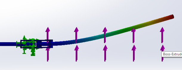
Advanced MatLab scripts and FEA were used to determine the wing profile and shape. Thin aerofoil theory and finite wing theory were captured in scripts and used to optimise the final profile. Stability and handling were evaluated in XFLR, an aircraft modelling program, to evaluate the wing placement, sweep, and taper. Control surfaces were sized according to MatLab simulations and were designed to control the aircraft in gusts of up to 10 kts.

The structural wing design is a careful compromise between weight, strength, and aerodynamic efficiency. Different approaches lead to wildly varying wing designs – no two wings are the same. Our analysis of the wing requirements led us to specify a very strong wing – one which would stand up to turbulence, transport, assembly, and landing loads without any risk of deformation or fracture. The challenge then came in reducing the weight of the wing to an acceptable level for low-speed flight.
Here we implemented one of the unique aspects of the aircraft. The wing was designed as a two-part fibreglass composite shell, with a spar and ribs providing strengthening. A composite wing in this style had never been completed before, but the achievable strength/weight ratio dwarfed any foam or mylar alternatives, providing solid resistance in the case of a hard landing or high-g turn. The manufacturing process was carefully planned and documented, and the assembly process checked with drawings and CAD to ensure that the timed aircraft assembly could be completed as quickly as possible.
Control
XFLR was used to calculate the stability and control matrices of the aircraft across a range of different attitudes and speeds. We built a MatLab flight dynamics model, implementing the 3D equations of motion of the aircraft, to study the response to perturbations, and to tune the Arduino PID control. With no way of testing prior to the first flight, such a model was immensely valuable in determining the optimal PID coefficients and checking the response of the aircraft in different conditions.
The Arduino flight computer was developed with a Kalman filter in mind. However, to reduce the amount of code required, and to limit the amount of testing necessary to get the filter tuned, a complementary filter was used instead. This combines data from accelerometers and gyroscopes to calculate the angular and linear position and rate of the aircraft. By combining the sensor data, the output is smoothed so that noise has less effect on the results, and avoids challenges such as gyroscopic drift.
The PID control uses a matrix of coefficients, defining the position of every control surface based on the derivative, proportional, and integral terms of the state error. State error is found by calculating the difference between the actual state – the output of the complementary filter – and the target state, which is defined pre-flight to be a straight and level flight state. The PID was tuned using the aircraft model.

In order to fit everything efficiently onto the Arduino Mega, significant changes were made to the sensor libraries. This reduced the amount of space they took up by nearly 1 kB, leaving this space available for data logging. The space that was saved was used to store a history of the aircraft response to control inputs. While the shakedown flight was taking place, the aircraft was under pilot control, and we used this historical data to fine-tune the PID coefficients. The PID coefficients are functions of the control derivatives, so by determining these more accurately in-flight the PID could be tweaked so that it was closer to the model we had intended. The aircraft had a very basic artificial intelligence system on-board – it would ‘learn’ how it responds to control inputs, and adjust its behaviour accordingly.
Manufacture
The most challenging aspect of the manufacturing was the composite wing. The process was carefully planned: foam moulds were cut, prepared with a release agent (black sacks work surprisingly well) and the fibreglass was cut to the right size. When everything was cut and laid in place, the resin was mixed and applied into the glass fibres. The resin was pressed through the two plies of fibreglass and spread throughout the matrix.

The wings were made in two parts – the upper and lower surfaces were made separately so that the moulds could be separated afterwards. The four resulting surfaces were nearly flat, which made it very easy to apply pressure throughout the moulds and force the resin through the matrix as it cured.
The fibreglass was released from the moulds after curing, and was then bonded to a range of carefully designed and laser-cut ribs. The ribs held the surface of the wing in the right shape, adding a small amount of torsional stiffness and providing mounting points for all of the hinges and servos mounted inside. A carbon fibre spar fitted through the ribs, and significant effort went in to getting a perfect press-fit to allow the wing to remain rigid in flight, but be easy to assemble and disassemble on the flight day.

The wing attachment mechanism was carefully designed, including unique 3D printed spacers and threaded rods to hold the wing onto the fuselage. The mechanism was very light, saving over 100 g against some of the more complex 3D printed clamps used by other groups. The electronics were very carefully planned and put together with a modular design providing flexibility and good assembly speed.
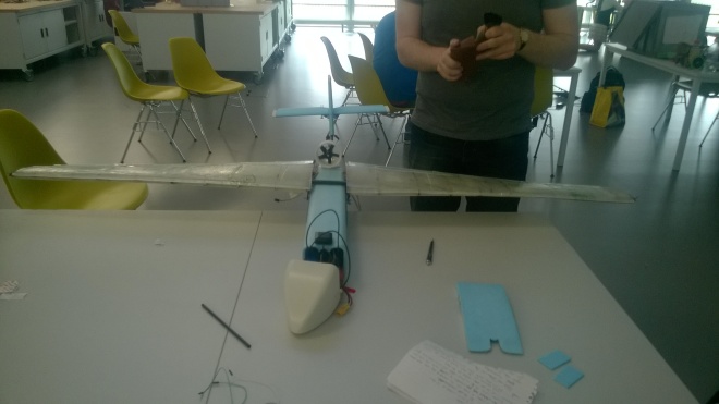
Flight Testing
On the day of the flight test, the aircraft was assembled and prepared for flight. The conditions were not ideal – winds were strong and gusting. They peaked around lunch, just as we were lining up for launch. The first few seconds of flight were smooth and well controlled, and the aircraft responded well to the pilot’s inputs. However, a 13kt gust after a few seconds forced it into a sideslip, and the small tail on the provided fuselage was not enough to correct the slip before the plane hit the ground.

Later analysis showed that the aircraft performed as expected given the conditions – it simply wasn’t specified to deal with the conditions it faced. The altitude loss given the gust was not excessive, but since it occurred immediately after take-off there was not enough height to regain control.
The crash showed the robustness of the wing – the fibreglass structure was not damaged at all in the crash and could have flown again… If the fuselage hadn’t snapped and the internal electronics disintegrated as it hit the ground.
Evaluation
A number of new and novel concepts were developed for the aircraft, and it broke new ground in a number of fields (double entendre very much intended). All of the design work and validation came together to produce an aircraft which behaved as expected – unfortunately in conditions it wasn’t designed for.
The project as a whole required a very interesting approach to project management – the electronics, wing, and controls were largely independent in their operation on-board the aircraft. The coupling occurred in the design phase, where the sizing of components and the layout of electronics affected the wing design. The wing layout and modelling also influenced the control systems.
The modelling that was done to ensure that the aircraft performed properly, and to tune the control systems, was very advanced and proved to be a reasonable challenge. It required a different approach to many time-dependent models due to the impact of the controls. The post-flight analysis and correlation checks between flight data and models showed the difficulty of dealing with sensor noise and environmental impacts on the aircraft.
The challenge itself also showed that getting an aircraft to fly is not a huge challenge – anything with a decent wing and a centre of gravity in the right place will fly. However, building something robust, reliable, and efficient is a much bigger task. There is a big difference between a working aircraft and an optimal aircraft, and the latter requires careful specification because it can easily be taken out of its comfort zone.
The bottom line is that this design and manufacture task has allowed a showcase for a huge number of different skills and tools. Designing a UAV is relatively easy, designing an autonomous UAV is hard, and designing a robust, efficient UAV is a significant challenge.
